《QSC-CX4-pwr-sm维修电路原理图.pdf》由会员分享,可在线阅读,更多相关《QSC-CX4-pwr-sm维修电路原理图.pdf(89页珍藏版)》请在收音机爱好者资料库上搜索。
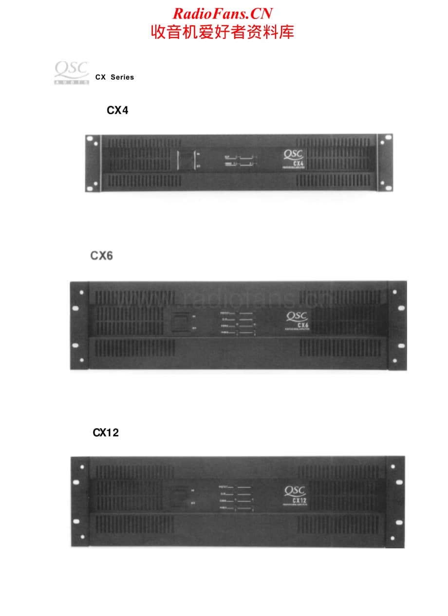
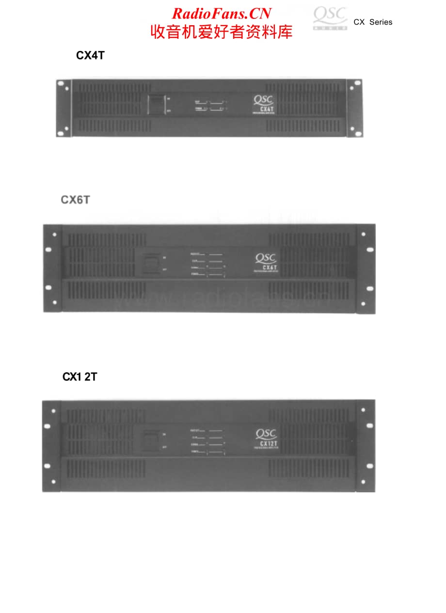
1、CX Series CX4 CX12 RadioFans.CN 收音机爱 好者资料库 CX Series CX4T CX1 2T RadioFans.CN 收音机爱 好者资料库 CX SERIES AMPLIFIER SERVICE MANUAL CX4 - CX4T CX6 - CX6T CX12 - CX12T QSC Technical Services Wats: 1-800-772-2834 Local: 1- 714- 957- 7150 Fax: 1-714-754-6173 QSC Online! Online Computer Information System 1- 80
2、0- 856- 6003 I- 71 4- 668- 7567 QSC Audio Products, Inc. 1675 MacArthur Blvd. Costa Mesa, CA 92626 RadioFans.CN 收音机爱 好者资料库 RadioFans.CN 收音机爱 好者资料库 CX Series Chassis Drawings CX4 Chassis Assembly .42 CX4T Chassis Assembly .45 CX6 direct outputs 45Hz* - 16kHz, +0, 3dB ; isolated outputs *Low Frequency
3、 is limited by 18 dB/octave 45 Hz high pass filter 200 ( direct outputs) 1 00dB below rated output (20 Hz to 20 kHz) 10k ohms unbalanced and 20k balanced Standard 19” Rack Mounting 3.5” (13.3 cm) 5.25” (13.3 cm) 17.9” (45.5 cm) 17.9” (45.5 cm) 46/2162/28 40/18.255/25 5.25” (13.3 cm) 17.9” (45.5 cm)
4、75/34 67/30.4 RadioFans.CN 收音机爱 好者资料库 CX Series I n t r o d u c t i o n This manual is prepared to assist service personnel with the repair and calibration of the CX Series power amplifiers The procedures described in this manual require advanced technical experience and sophisticated audio test equ
5、ipment. AA CAUTION: To reduce the risk of electric shock, do not remove the cover. No user- serviceable parts inside. Refer servicing to qualified service personnel. WARNING: To prevent fire or electric shock, do not expose this equipment to rain or moisture. Documentation This manual contains schem
6、atics, printed circuit board (PCB) drawings, parts lists, and mechanical assembly drawings. This information should be used in conjunction with the test and troubleshooting guide. The electrical and electronic components are identified by circuit identification numbers on the schematics and the part
7、s list, The test if over 3VDC present, the protection circuit is operating normally to hold of operation. See DC FAULT WITHOUT CURRENT DRAW section to fix this DC fault. l RELAY WONT TURN ON WITH NORMAL OPERATING AMPLIFIER: 1 .Check Relay power voltage. With relay off, voltage at C516 should measure
8、 about 47VDC. With relay on, C516 should measure about 27V. if not check D516, R531, C516, D515. 2. If relay power voltage OK; check voltage on the timing capacitor C515. Should rise to 12- 15VDC, in three seconds, which triggers Q513. If not check R528, R530, C515 polarity 3.Timing voltage OK; chec
9、k relay transistor Q512. If good, RN501 B- C resistors from base to speaker bus should activate relay. 4. Relay driver Q512 OK, check driver Q513 and LD1 01. l NO RED “PROTECT” LED 1. Check LED voltage, If over - 2V, LED is defective. If OV with relay off (no negative voltage to LED), there is no “p
10、rotect” power (open or missing R534), which defeats shutdown circuits. Be sure to correct before proceeding. l NO MUTING DELAY (be sure “protect” LED works) ALSO WITHOUT THERMAL OR DC PROTECT: relay or circuit is “stuck on! 1, Relay Q512 shorted or wrongly mounted. Check by jumping base to emitter,
11、should turn it Off. 2. Relay Q513 shorted or wrongly mounted. Check by jumping base to emitter, should turn it Off. NO MUTING DELAY ONLY (all else OK): 1. D518 reversed ( charges timing capacitor C515 immediately) 2. R528 low (fast C515 charge) 3. R29 low (low voltage on E7 turns Q513 on too soon),
12、missing or high R30 (no off current). EXCESS MUTING DELAY: 1. Check timing capacitor E515 voltage, If it rises normally but circuit is slow to turn on, check D517 (lift temporarily), LD501 bad or intermittent, RN501 D too low. 2. Timing capacitor voltage wrong; determine cause (R528, R530, reversed
13、C515, reversed or wrong Q511. l NO THERMAL SHUTOFF Short the amplifier load with full signal to raise heatsink temperature and put voltmeter across PTC R516 or input RN902, (CX4/T) RN500 is wrong value. (Faulty input resistors will cause the amplifier to fail the Common Mode test.) 2. Too low: Above
14、 feedback values wrong or shunt resistor R541/C520, (CX4/T) R523 wrong or open (open causes very low gain with instability. Check circuit trace). l POOR FREQUENCY RESPONSE (Be sure to correct any gain problem first) 1. High frequency, determined by feedback capacitor C519, (CX4/T) C516 (wrong value
15、also causes instability) 2. Low frequency, determined by DC feedback rolloff C520, and “butterworth” feedback compensation network C518/R542. (CX4/T) C502 low frequency rolloff. l STEP CIRCUIT (CX12/T only) Check step circuit components U501, U502, Q503, Q504 carefully, note exact output voltage whe
16、re step cuts in (are both matched to 1V). Step turning on too late (too high) will hang up at 2 ohms. Check referent 15V zener voltages D509 and D510. After inspecting all parts, see below: 1. Step distortion: check step filter components R508/C505, R504/C501, and C528. 19 RadioFans.CN 收音机爱 好者资料库 CX
17、 Series 2. No step: check 0503, Q504, U501, U502 burned to open. R505, R506, R510 open. Instability (Gain problems, spurious noises, and oscillations) All Models l General Output Distortion l Excessive or unbalanced crossover - Output waveform appears “fuzzy” Possible Causes: First, distinguish betw
18、een instability (fuzziness), “ringing” which is momentary instability after a transition, step” distortion, crossover distortion (both often show ringing), or general distortion. l GENERAL OUTPUT DISTORTION SEVERE: All loads, often with current draw: often associated with feed back components (U503,
19、 C532, C520, C519, C518, C523). (CX4/T) U501, C516, C505. Check resistor values on R540, R541, R542, R568, R538, R547. (CX4/T) R502, R523, R524. MEDIUM: Check feedback capacitor C519. (CX4/T) C516, LOW GAIN: Suspect open circuit in feedback shunt R541 and C520. (CX4/T) R523. Check for broken circuit
20、 trace. Substitute IC and check IC socket for contamination. l EXCESSIVE OR UNBALANCED CROSSOVER (Excess notch or ringing at zero crossing) 1. Severe: shorted bias diode D505, D506. (CX4/T) D504, D505. 2. Moderate: Out- of- spec bias diodes. 3. Defective bias trimmer components VR501, R511. (CX4/T)
21、R512, R532. 4. Check for open base resistors R517, 518 on output devices. (CX4/T) R504, R527. l OUTPUT WAVEFORM APPEARS FUZZY 1. Check main heatsink ground continuity with chassis ground, 2. High frequency snubbers defective (C513, C514, R525, R526, R523, R527). (CX4/T) R520, C515. 3. Check capacito
22、rs on speaker output board. 4. Check/adjust driver emitter capacitors C519 and C523. (CX4/T) C516, C505. 20 RadioFans.CN 收音机爱 好者资料库 CX Series Power Supply and Voltage Rail Balancing (Uneven rails and power supply problems) Symptoms: - Current limiting wrong l Current limiting too high into a short .
23、 IC rail too high into a short - Current limiting too low into a short l Uneven voltage rails Possible Causes: l CURRENT LIMITING WRONG Current limits should remain high down to 2 ohms, and collapse to a lower value for short circuits. This is caused by the IC rails going from normal 14 - 1.5 volts


- 配套讲稿:
如PPT文件的首页显示word图标,表示该PPT已包含配套word讲稿。双击word图标可打开word文档。
- 特殊限制:
部分文档作品中含有的国旗、国徽等图片,仅作为作品整体效果示例展示,禁止商用。设计者仅对作品中独创性部分享有著作权。
- 关 键 词:
- QSC CX4 pwr sm 维修 电路 原理图
 收音机爱好者资料库所有资源均是用户自行上传分享,仅供网友学习交流,未经上传用户书面授权,请勿作他用。
 QSC-CX4-pwr-sm维修电路原理图.pdf


 Crown-XLS202-pwr-sch维修电路图 手册.pdf


